Technical specifications
Hereafter, we provide all details about sensors present in our dataset. This includes their type, their capture rate, their unit, their reference frame and the sensor positions. Details on how they are stored in the dataset are given on the Data organization page.
This page is organized as follow:
- Sensors positioning and Frames of reference definition
- Positioning data
- Visual data
- Semantic segmentation classes
- Summary table
Sensors positioning and Frames of reference definition
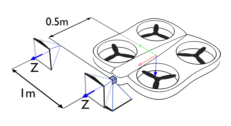 Figure 1: Sensors position
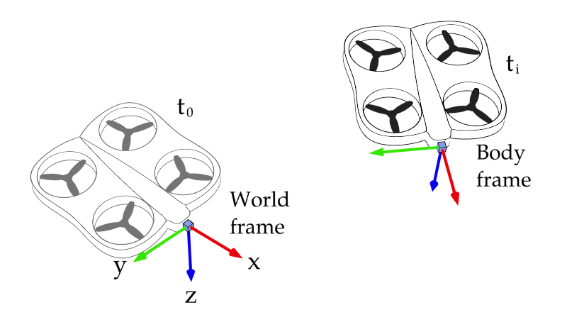 Figure 2: Frames of reference definition
Figure 1 shows the sensor locations on the drone used to generate our dataset. Cameras are represented by the pyramids. The blue cube shows the IMU and the GPS receiver locations.
Figure 2 illustrates the frames of reference used for all position-related data. The World frame is defined at the starting point of the trajectory and oriented such that the drone yaw is equal to zero. Other axis are horizontal. The Body frame is rigidly attached to the drone with its origin corresponding to the position of the IMU and GPS receiver. All frames use the North, East, Down (NED) axes convention.
Positioning data
For all position-related data, we use the North, East, Down (NED) axes convention. Distances are expressed in meters, rotations in quaternions, angles in radians, and time in seconds. The positioning information stored in the dataset is as follows:
- Ground truths for the position, speed, acceleration, and attitude are expressed in the World frame;
- Angular velocity ground truths and IMU data, i.e. acceleration and angular velocity are expressed in the Body frame;
- GPS position and speed are given in meters in the World frame.
It is important to note that the GPS position is not given by the standard longitude, latitude and altitude information, but by a simple position in meters expressed in the World frame. This position in meters is obtained by projecting the position given with the longitude/latitude/altitude format relatively to the first point of the trajectory.
Additionally, our dataset stores some information about the state of the sensors. The following sensors data are made available:
- An estimate of the initial bias for the accelerometer and the gyroscope;
- The GPS signal quality estimates (i.e. GDOP, PDOP, HDOP, VDOP) for each measurement;
- The number of satellites visible by the GPS receiver for each of its measurements.
Visual data
Each trajectory record comes with eight video streams corresponding to the (1) left, (2) right and (3) down-looking RGB camera views and the (4) segmentation, (5) depth, (6) normals, (7) disparity and (8) occlusion maps seen by the left camera. Each video stream consists in a set of successively numbered pictures stored in a dedicated directory. The image formats and content are the following:
- RGB pictures are stored in JPEG images.
- Occlusion masks are stored as lossless 1-channel PNGs.
- Surfaces normals are stored as RGB lossless PNG files. Normal vectors are tri-dimensional and are expressed with respect to the Body frame. Red color corresponds to the Y-axis, blue to the X-axis, and green to the Z-axis (but with reverse direction). All vectors were normalized to have a unit norm. In order to fit in an RGB picture, the range of possible element values, i.e. [−1; 1], was scaled and shifted to fit a range of [0; 1]. For example, with this convention, a perfectly flat and horizontal surface will have an RGB color corresponding to (0:5; 1; 0:5) if the drone does not have any pitch nor roll angle.
- Depth and stereo disparity maps are expressed in meters and in pixels respectively and are stored as 16-bit float matrices in lossless 1-channel PNGs. One of the provided example scripts shows how to decode them.
- Semantic segmentation maps are stored as lossless 1- channel 8-bit unsigned int PNGs. The value of a pixel indicates a label number. Correspondences between label numbers and classes are given below.
Camera intrinsic matrix
The cameras used to record visual data all share the same intrinsic matrix. For an image of height \(h\) and width \(w\), this matrix is given by: $$\mathbf{K} = \begin{bmatrix} f_x & 0 & c_x \\ 0 & f_y & c_y \\ 0 & 0 & 1 \end{bmatrix} \quad \text{with} \quad f_x=c_x= w/2 \ \text{and} \ f_y=c_y= h/2 $$ This corresponds to visual field of view of 90 degrees.
Semantic segmentation classes
| Id | Class content |
|---|---|
| 1 | Animals |
| 2 | Trees |
| 3 | Dirt ground |
| 4 | Ground vegetation |
| 5 | Rocky ground |
| 6 | Boulders |
| 7 | [empty] |
| 8 | Water plane |
| 9 | Man-made construction |
| 10 | Road |
| 11 | Train track |
| 12 | Road sign |
| 13 | Other man-made objects |
Sensors summary table
| Data | Sampling freq. | Ref. frame | Unit | Misc. |
|---|---|---|---|---|
| Ground-truth position | 100Hz | World | [m] | |
| Ground-truth velocity | 100Hz | World | [m/s] | |
| Ground-truth acceleration | 100Hz | World | [m/s²] | |
| Ground-truth attitude | 100Hz | World | [quaternion] | |
| Ground-truth angular velocity | 100Hz | Body | [rad/s] | |
| IMU acceleration | 100Hz | Body | [m/s²] | Initial bias estimate provided |
| IMU angular velocity | 100Hz | Body | [rad/s] | Initial bias estimate provided |
| GPS position | 1Hz | World | [m] | |
| GPS velocity | 1Hz | World | [m/s] | |
| GPS signal information | 1Hz | n/a | n/a | Includes number of visible satellites, GDOP, PDOP, HDOP and VDOP |
| Downward-looking RGB picture | 25Hz | n/a | n/a | 90° fov, Captured by downward-looking camera |
| Right stereo RGB picture | 25Hz | n/a | n/a | 90° fov, Captured by right camera |
| Left stereo RGB picture | 25Hz | n/a | n/a | 90° fov, Captured by left camera |
| Stereo disparity map | 25Hz | n/a | [pixel] | 90° fov, Captured by left camera |
| Stereo occlusion map | 25Hz | n/a | n/a | 90° fov, Captured by left camera |
| Depth map | 25Hz | n/a | [m] | 90° fov, Captured by left camera |
| Surfaces normal map | 25Hz | Body | n/a | 90° fov, Captured by left camera |
| Semantic segmentation map | 25Hz | n/a | n/a | 90° fov, Captured by left camera |